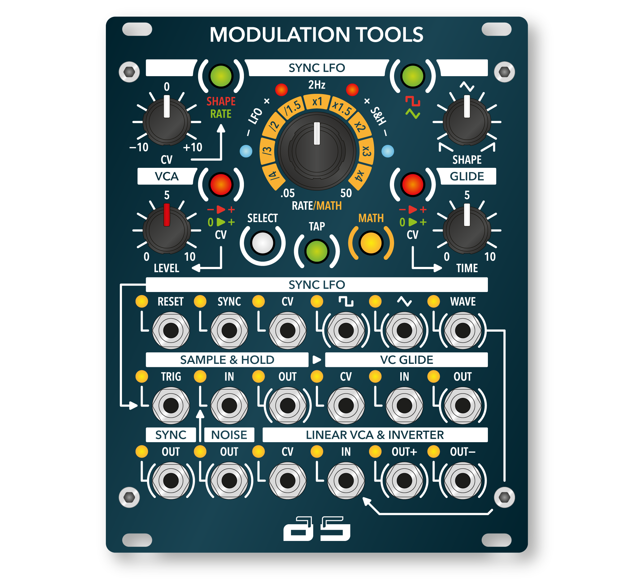


MODULATION TOOLS
The unit designed for generating and processing modulation signals includes a Sync LFO, a White Noise Generator, a Sample & Hold, a VC Glide, and a VCA & Inverter or Ring Modulator circuits. These submodules are internally pre-wired and closely integrated, but the internal connections can be broken using the front-panel jack connectors, allowing each section to operate independently.
The Sync LFO simultaneously generates two distinct waveforms: triangle (TRI) and square (SQR). These are available on separate outputs, along with a third output offering a selectable waveform. The module features RESET, SYNC, and CV inputs. The CV input can be used to control the waveform shape, the LFO frequency, or its divider. The frequency range is adjustable between 0.05 Hz and 50 Hz. The TRI waveform can be continuously morphed from SAW to RAMP, while the SQR waveform’s pulse width is also adjustable.
The output of the Sync LFO is routed to the input of the VCA & Inverter, enabling control over the LFO’s modulation depth. Additionally, the VCA can operate in Ring Modulator mode. The
Sync LFO also includes a SYNC output, whose frequency can match the LFO frequency or be a multiple or division of it. This output drives the TRIG input of the Sample & Hold circuit, with its behavior configurable via the Hidden Parameter menu.
The analog White Noise Generator is directly connected to the input of the Sample & Hold. The output of the Sample & Hold is then routed to the input of the VC Glide. The VC Glide allows adjustment of both the glide time and the amount of control voltage (CV) applied.
Module features of ASR401 MODULATION TOOLS:


Block diagram of ASR401 MODULATION TOOLS:

Owner’s manual:
![]()
Be the first to review “MODULATION TOOLS”
You must be logged in to post a review.
Related products
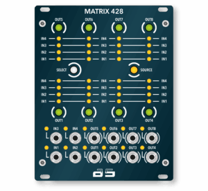
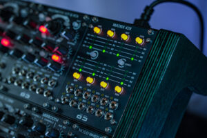
This module is designed for stage use and managing complex patches. Its main purpose is to eliminate the need for physically rearranging patch cables. With the help of snapshot functions, it can dynamically reroute connections within a single patch. The MATRIX 428 features four inputs and eight outputs, all capable of routing audio, CV, and [...]
High-Performance Power Supply for Adamsynths™ Warthog Modules and System. The ASR-PSU is a high-performance power supply designed specifically for the Adamsynths™ Warthog modular synthesizer system, engineered to meet the elevated power demands of its advanced modules. Due to the complexity and functionality of the Warthog modules — particularly those supporting Total Recall — the system [...]
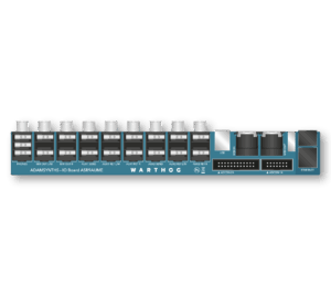
The ASR9AUME Outboard is the dedicated outboard interface of the Warthog system, providing external connectivity for both the Mixbooth and the Central Unit. All connectors are located on the rear panel of the Warthog for convenient access, without interfering with patch cabling or module operation. Mixbooth Connectors: Stereo Headphone Output Stereo Main Output 2 AUX [...]
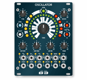
The OSCILLATOR is a robust, high-stability, SAW core, through-zero analog VCO. Its symmetrical waveform outputs are DC-coupled, meaning they are capacitor-free. The waveform output level is 10 Vpp. This is an audiophile-grade solution that ensures distortion-free waveforms across the entire spectrum. The oscillator’s full frequency range spans 10 octaves, with a deviation of ± a [...]
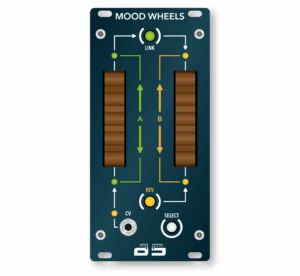
Two wooden control wheels designed for morphing between snapshots and modulating that morphing process. Mood Wheels allows you to completely reshape the sound of the Warthog within a single patch, making the music more expressive and alive. It’s called “MOOD” rather than “MOD” for a reason — this is about shaping the mood, not just [...]
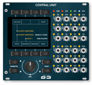
This module serves as the central hub of the Warthog system. It facilitates communication between modules, handles MIDI–CV conversion, and provides the unique Adamsynths™ TOTAL RECALL feature, allowing patches to be saved and recalled. The interface includes navigation and function buttons, an encoder, a 2.8-inch touchscreen display, and 12 analog CV outputs alongside 12 “digital” [...]


The Adamsynths™ Warthog is an analog modular synthesizer equipped with Total Recall technology. It is the first analog modular synthesizer in the world to feature full patch memory and recall. And yes. This is not a digital platform. Not a virtual modular synthesizer. This is a 100% analog sound engine, Eurorack format, plug & play [...]
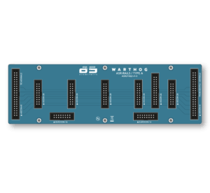
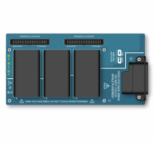
Electronic Distribution System for Adamsynths™ Warthog Modules and Eurorack Compatibility. The ASR-RAILS is a dedicated electronic distribution layer developed for the Adamsynths™ Warthog modular synthesizer system, responsible for both power delivery and the physical infrastructure of PatchCon internal communication channels. Due to the elevated power requirements and inter-module communication demands introduced by Total Recall, Warthog [...]
Reviews
There are no reviews yet.